Essentials of Computer Architecture and Assembly
Table of Contents
This article simplifies/skips a lot of things. It is mainly intended to make picking up assembly easier. Also, this is a write up of what I have learned and understood over the course of reading CS:APP book and doing some assembly exercises on Windows.
Note: This article is work in progress. I am filling the missing sections in my free time.
Introduction
This guide is a mix of topics from computer architecture, operating systems, and assembly programming.
CPU
The CPU, or Central Processing Unit, is a unit of computer hardware that executes instructions. It is the "brain" of a computer system.
However, it is not much clever as brain is. What it does is just to fetch next instruction, decode it, and execute it. That's it. This is called the fetch-execute cycle.
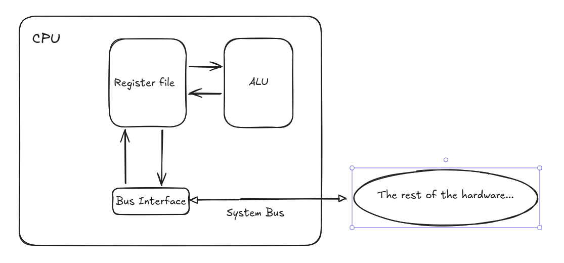
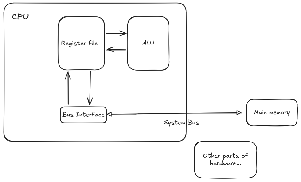
In a simple model of single CPU which executes instructions sequentially, one at a time, the CPU mainly consists of small memory, decoder, and Arithmetic Logic Unit (ALU). It is also connected to an intermediary called System Bus which connects the CPU to the other components in a computer hardware.
The ALU is the unit responsible for carrying operations like addition, subtraction, multiplication, etc.
The memory of CPU, called register file (or just set of registers), is the set of fastest memory elements in computer hardware which are used for storing operation results, intermediate results, addresses, or any value that fits their capacity.
Analogously, if we say a CPU is a person solving a math problem, then register file (the set of registers) is a collection of scratch papers.
Below is a simplified diagram.
Registers
We can talk a lot about registers.
So, what is a register? A register is a storage with a fixed capacity (in bits). It just stores plain bits.
There are mainly two types of CPU registers: General Purpose and Special Registers.
General Purpose Registers (GPRs) are those we are given access to, while special registers are mostly limited to the usage by the CPU.
One important register is called Program Counter (or instruction pointer). It stores the address of the next instruction.
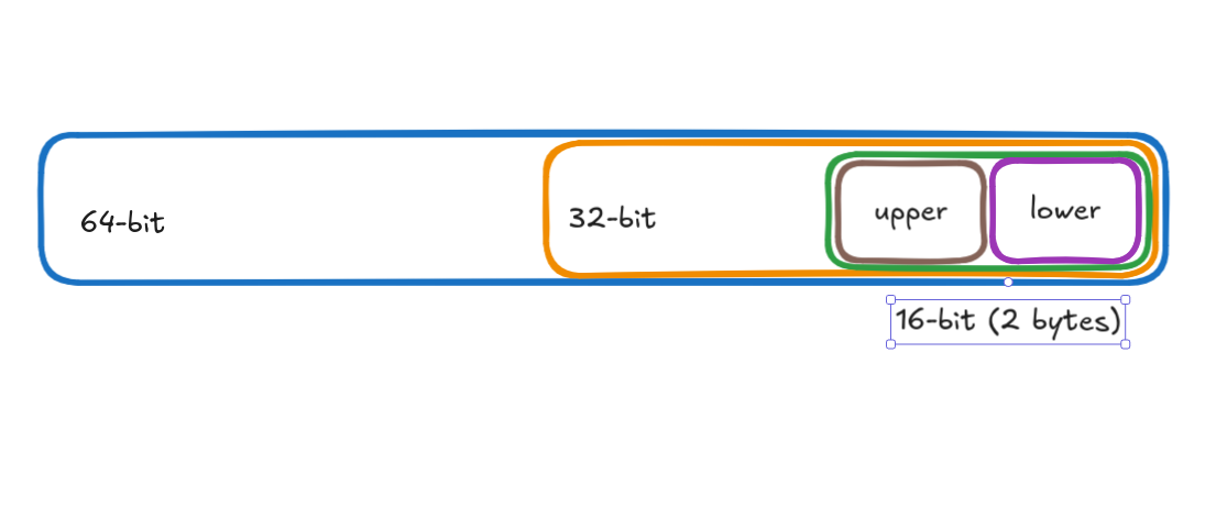
In x86-64 systems, registers typically have capacity of 64 bits. Due to historical reasons, in terms of access, they are "divided" into parts: lower 64-bit, lower 32-bit and lower 16-bit.
The lower 16-bit itself has upper and lower bytes. This means we can use the upper byte or lower byte -- directly. In contrast, some GPRs do not have this support of directly using the upper byte of lower 16-bit.
This division gives us the ability to access/use the specified portions of registers. In other words, we can directly access parts contained in the boxes (yes, boxes).
Why is this due to historical reasons? As registers had lower capacity than 64-bit in the past, hardware manufacturers modernized the processors with backward-compatibility in mind so that old programs could run on newer processors.
Note, this "division" is crucial -- since we quite often use them in assembly.
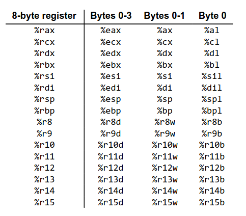
Below is a diagram presenting some of registers in x64 (source).
Instruction Set Architecture
The next important element is ISA, or Instruction Set Architecture. For CPUs to be useful, they need to execute instructions. I define an instruction as a set of rules that specify which operations to carry on and on what operands.
The ISA provides the set of such instructions the CPU can understand and execute.
This provides us with a powerful abstraction over CPU. Also, it enables us to view the execution process as sequential, executing one instruction at a time. In reality, the modern CPUs are quite sophisticated and even support executing multiple instructions simultaneously.
In conclusion, ISA is the asset for us to talk to the CPU.
Main Memory
One may note that registers are quite small and not enough for large sizes of data our computers process on daily basis.
Thus, we need a larger memory, and it is called the main memory. However, compared to registers, the access time to main memory is quite slow. This is a trade off.
For now, we assume that the main memory is a very large array of bytes we can address and access. In fact, this is how our programs view the memory (moer about it later).
Keep in mind this assumption as it is very important in assembly.
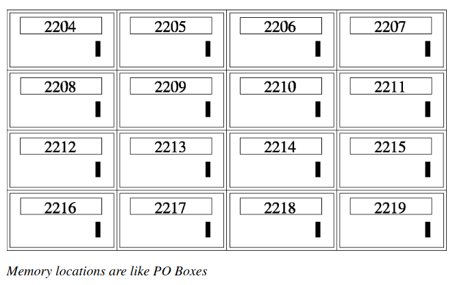
Below is a diagram depicting the memory as Post Office boxes from the book Programming From Ground up. As you can note, each box has an address (or, an identifier/label) associated with it.
One question arises: how do we address memory and how much can we have of memory? The answer is what the "X" means when we say "X-bit architecture".
What "X" means in "X-bit architecture"
Looking at the organization of registers, one may note that X-bit system mainly has registers with capacity of X bits. In other words, X-bit system can handle X-bit sized data at once.
Another meaning which follows from the size of registers is how many addresses we can have for our memory locations.
Using basic counting from math, we can derive that 64-bit system can address 2^64 bytes of memory. Note, this is not bits, but bytes. This is because each memory location is one byte in capacity. In the analogy of Post Office Boxes, we can have 2^64 boxes with unique addresses and each having 1 byte of capacity.
If you're confused about addresses and calculation, think of addresses as "labels" to locations. So, we can label 2^X memory locations, reuslting in memory as large as 2^X * capacity_of_single_location.
Subsequently, with 32 bits we can have memory as large as 2^32 * 1 byte ~= 4GB while with 64 bits theoretically we can have 16 exabytes!
Main memory: smaller, faster, and volatile (data is lost when a system goes off). Secondary memory: larger, slower, and non-volatile (data persists).
As you may have noticed, the smaller is the memory, the faster it is; the larger is the memory, the slower it is (in terms of access time). This is part of the memory hierarchy.
The main memory can be in form of RAM, while secondary memory can be HDD, SSD, etc.
Our model so far...
Intro to Assembly
Remember that the CPU's main task is to fetch, decode, and execute instructions. Reminding again, the ISA of each CPU provides instructions valid for that CPU.
Now, how do we write those instructions for CPUs? As you may already know, CPUs only understand 0s and 1s, which is machine-language. Nothing more. Just bit patterns + context (with context, for example, numbers may denote letters).
However, as humans, it could be burdensome to talk to CPUs in plain bits. Here, the Assembly language gives us one higher level of abstraction and makes writing instructions much more readable, essentially being a wrapper over the machine language.
As our instructions are based on the ISA of our machine, assembly written for different ISAs is not the same, and incompatible.
Therefore, assembly is machine-dependent. In this sense, we can call assembly a machine language to distinguish from higher level languages such as C which are much more machine independent.
There are many variations of assembly language, differing in syntax and some features. However, the idea is the same: just write the instructions for the CPU.
I am going to use NASM syntax.
In the following sections, I write about the most essential assembly concepts, but without giving full program code. Just bare plain concepts.
Movement operations
The main operands of instructions is data. One of the most common operations we do is data movement/copy/write/read.
The instruction that copies data from one source to destination in assembly
is called mov with the following form:
mov DATASIZE dest, srcThe operation copies bytes of amount specified using DATASIZE from source src to dest.
Although this definition covers all operand forms, we will see that there is subtlety in
how the process looks like depending on operand forms (the operands are dest and src).
Since we to specify data sizes and that they are very important in other instructions too, the following section presents some of the data sizes.
Common data sizes
| Name | Size | Size (bits) | NASM |
|---|---|---|---|
| byte | 1 byte | 8 bits | op byte |
| word | 2 bytes | 16 bits | op word |
| dword | 2 words | 32 bits | op dword |
| qword (quad word) | 4 words | 64 bits | op qword |
Example:
mov dword dest, srcThis instructions reads 4 bytes of data from src and write 4 bytes to dest.
Operand and instruction forms
In assembly, there are mainly three types of operands:
- register
- immediate
- address in the program memory
The instructions we write are:
- binary -- takes 2 operands
- unary -- takes one operand
The mov instruction is binary. Thus, its operands are the mix of three, with some combinations disallowed.
The following is the table of usage patterns.
| Type | Form | Value in operation | Meaning | Explanation |
|---|---|---|---|---|
| Immediate | Imm | Imm | literal value | - |
| Register | r | R[r] | Value stored in register r | - |
| Mem | [Imm] | M[Imm] | Value stored at memory address Imm | - |
| Mem | [r] | M[R[r]] | Value stored at memory address stored in r. | The register r stores a memory address as its value.Writing [r] means that r stores memory address and instructs CPU to work on data stored in that address. |
| Mem | [r1 + r2*k + Imm] | M[R[ r1 ] + R[ r2 ] * k + Imm] | This is arithmetic involving addresses. | This form presents generic form for calculating address and accessing value starting at it in memory. For example, setting k and Imm to 0, we obtain the (2) form in the table. |
The following are diagrams explaining behavior of mov operation involving different operand forms.
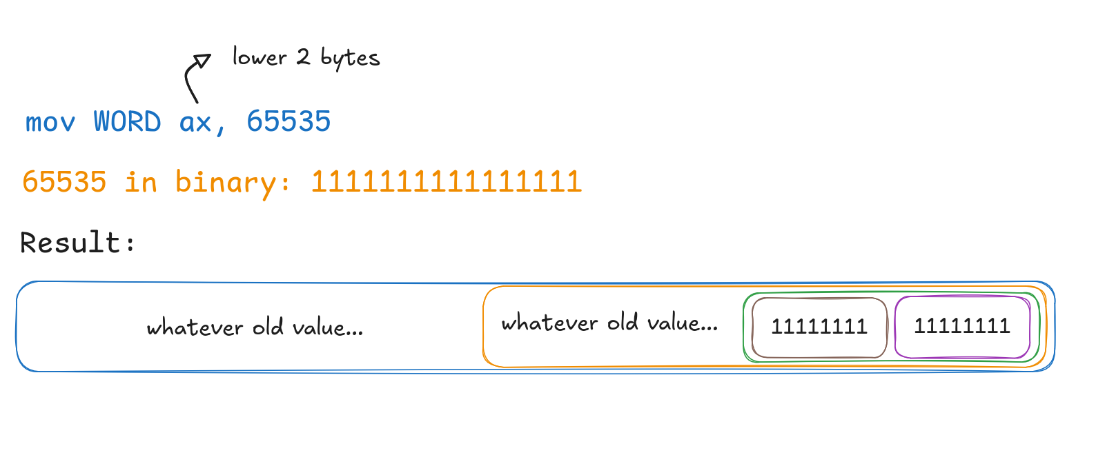
Immediate to register
Register to register
Description: copies value from src register to dst register (note the size specifier).
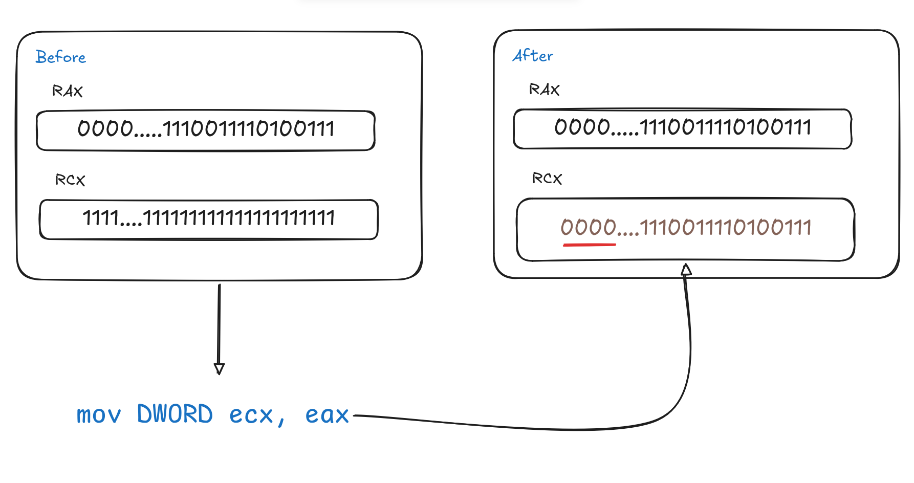
Note: the red underline is not accidental. This is one of the special cases which is discussed later.
Memory to register
Suppose we have the number 1324 in the memory locations shown in the image below. Such a signed integer is typically 4 bytes.
- 1324 in binary: 10100101100
To convert to hex, group the bits of the binary value by 4 from right to left and replace each group with hex equivalent. Fill in zeros from left when number of bits in a group is not 4.
0101 0010 1100
 0x5  0x2  0xC => 1324 in hex: 0x52c
Joining them by 1 byte groups:
00000101 00101100
   0x5      0x2c
Note: '0x' just denotes that the value is in hex.
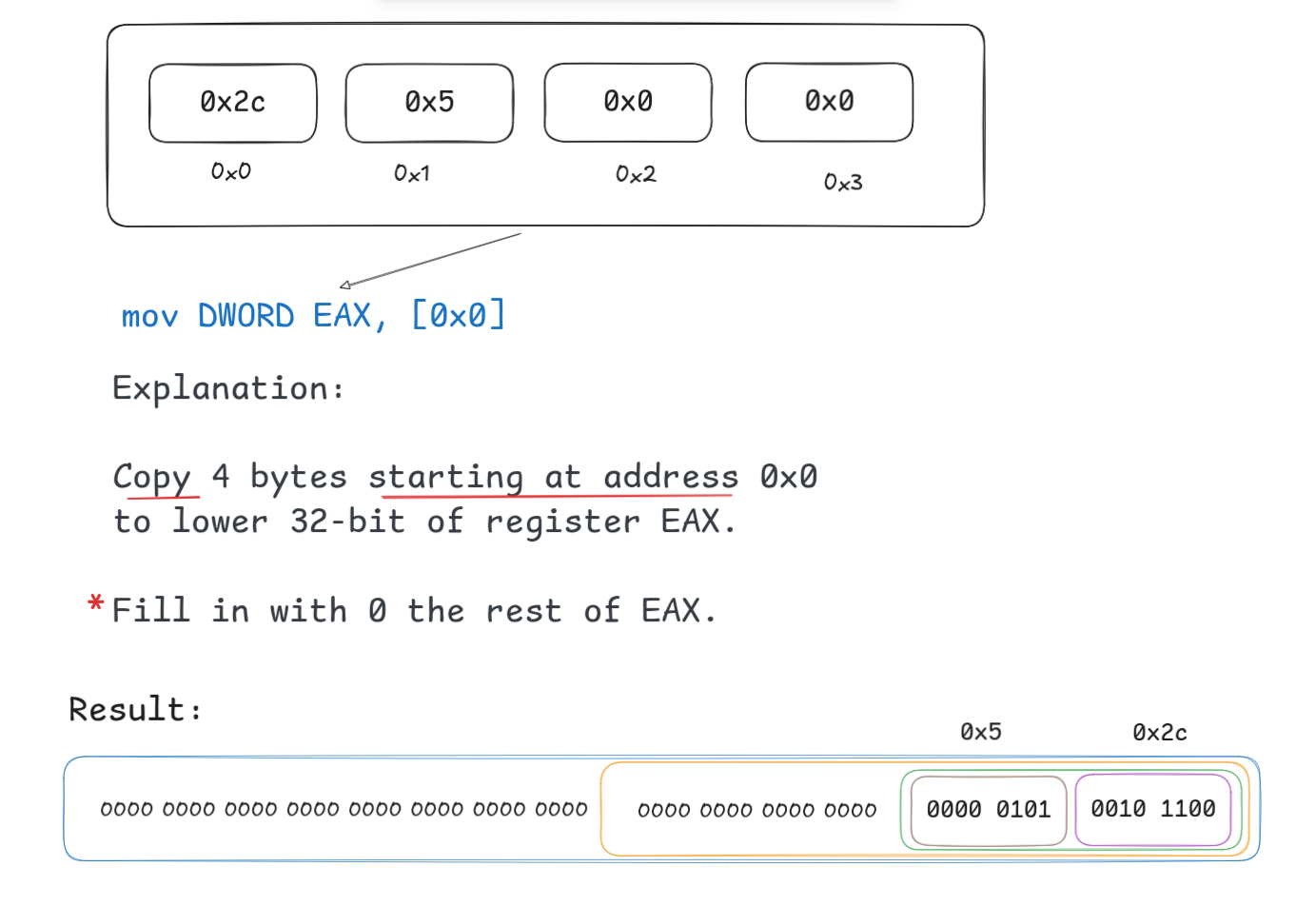
Note: You might have noticed little red asterisk. The sentence it is marking describes the behavior on one subtle case of mov operation. This will be discussed later.
Immediate to memory
Register to memory
Special cases
CMP/TEST operations
Coming soon.
Conditions/FLAGS
Coming soon.
Conditional branching: Intro to Jumps
Coming soon.
From Source to Binary
Coming soon.
Object File Structure
Back to Jumps
Conditional movement operations
Coming soon.
Into to Stack
Coming soon.
Hardware Manager: Operating System
Abstracting hardware: Process
Abstracting Memory: Virtual Address Space
Back to Stack
Some interesting things
Coming soon.
Resources
Coming soon.